Tere foorumipere!
Alates siis eilsest 09.11.2010 hakkasin ka mina Cadillac Seville 4,9V8 omanikuks ja proovin autot nüüd tasapisi korda sättima hakata.Esimene teravam mure on esimese ventilaatoriga,mis ei puhu.Eelmine omanik mainis,et viga puhuri kontrollplokis ja andis uue kaasa.Hakates siis vahetama blower resistorit avastasin,et uuel on mõlemast pistiku vastusest 1 klemm puudu.Siinkohal siis ka küsimus,kas keegi teab kas tegemist võib olla uuema Seville controlleriga ja kas on võimalus kuskil asi vanema tüübi vastu ringi vahetada, lepiks ka kasutatuga,kui töötab.Siinkohal märgin ka, et pole õrna aimu ka kus kohast või kuna uus ostetud,et sinna pöörduda.
http://nagi.ee/photos/239346/17014337/
http://nagi.ee/photos/239346/17014339/
Cadillac Seville -93 esimene ventilaator

Re: Cadillac Seville -93 esimene ventilaator
kas mingeid seerianumbreid ei ole peal? nende järgi vast tuvastaks ka.
„siin on tegemist jällegi ühe toreda riigireetmisega“ (Bretschneider).
Re: Cadillac Seville -93 esimene ventilaator
Nii uuel siis karbi kirjas GM# 12368389
Vahepeal sain veel niipalju tead,et näe,ise ka loll,vaatasin siis juhtme otsas olevaid vastuseid ja seal ka need kohad tühjad.Vanaga siis selline probleem,et kui panna kitsamasse pesasse juhe tagasi,siis vent huugab koguaeg põhjagaasiga ja seest nupudele rutjudes ei miskit,uuele juhtmed järgi,siis ei kippu ega kõppu.
Vahepeal sain veel niipalju tead,et näe,ise ka loll,vaatasin siis juhtme otsas olevaid vastuseid ja seal ka need kohad tühjad.Vanaga siis selline probleem,et kui panna kitsamasse pesasse juhe tagasi,siis vent huugab koguaeg põhjagaasiga ja seest nupudele rutjudes ei miskit,uuele juhtmed järgi,siis ei kippu ega kõppu.
Re: Cadillac Seville -93 esimene ventilaator
GM PART #12368389 A/C DELCO # 15-8548
* 1992-1996 PONTIAC BONNEVILLE
* 1992-1996 OLDSMOBILE 98 REGENCY AND 98 TOURING SEDAN
* 1990-1992 OLDSMOBILE TORONADO
* 1992-1999 OLDSMOBILE 88 REGENCY AND 88 ROYALE
* 1991-1993 BUICK REATTA
* 1992-1999 BUICK LESABRE
* 1992-1996 BUICK PARK AVE. AND ULTRA
* 1992-1993 CADILLAC DEVILLE
* 1991-1993 CADILLAC ALLANTE
DeVille-Seville-Eldo peaks jooksma sama elektri peal, elik võiks nagu sobida
Aga vana karbi number tuvastamatu?
„siin on tegemist jällegi ühe toreda riigireetmisega“ (Bretschneider).
Re: Cadillac Seville -93 esimene ventilaator
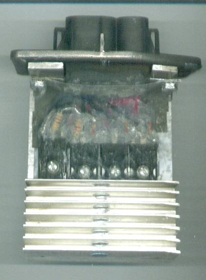
Nii nr. siis vana pealt
DELCO 16061602
STK6994J 161
7L 8750 JAPAN
DELCO 16061602
STK6994J 161
7L 8750 JAPAN
Re: Cadillac Seville -93 esimene ventilaator
seda enam ei tehta, asendusjupp kannab numbrit AC Delco #12484912
ilmselt sul miskine teise masina moodul siiski - neid pidigi kaks erinevat olema juttude järgi.
muide, Audi V8, p/n 443 820 523B kasutab sama juppi aga vaevalt meie Audi diiler sulle head hinda pakub.
keegi miki soovitas võtta ära 5 amprise kaitsme, PGM nimelise. Võid proovida, kas siis vana moodul toimib sooja mootoriga või kliima sisse lülitades.
Kaugelt otsitud võimalus aga proovida ikka maksab.
„siin on tegemist jällegi ühe toreda riigireetmisega“ (Bretschneider).
Re: Cadillac Seville -93 esimene ventilaator
Hmmm...aga huvitav kas aitab Forss,ega ei tea,kas kellegil võib mõni isend olla varuosadeks
Re: Cadillac Seville -93 esimene ventilaator
keegi miki süvenes asjasse ja tegi kättesaadavatest juppidest uue ploki (jutt siis DELCO 16061602):
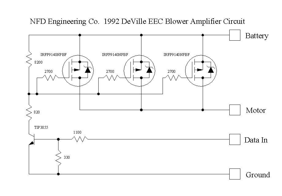
jutt ka juurde - ei viitsi ise sellisesse elektroonikasse eriti süveneda
Can't make it any simpler than this, just a NPN input driving three power MOSFET transistors with the input characteristics identical to the prototype. Seven resistors and four transistors. Why the TIP3055 for the input transistor instead of a cheap 2N3904? It's heat sink mounted like the other three and gives me three stiff terminals for mounted the loose components, the input circuit matches the OE and the circuit has a gain of less than unity. There is an advantage in this in that that low impedance input resistive circuit gives a much narrower trip point at the 2.8 V level like the OE. The 2700 ohm gate resistors give a gentle ramp in the turn on and off switching of the MOSFETS of about 20 microseconds. The resistive divider in the TIP 3055 cuts down the drain voltage for protection using the worse case value of 22 Volts with the Delco CS-144 alternator that is clamped at that voltage.
Was concerned about the MOSFETS operating in the linear mode, but forgot I was designing this thing for myself and not for production, the linear mode is where these transistors can be half on or half off causing excessive power dissipation and would have to do that if price were the object, only use one power MOSFET instead of three, so it cost me a couple of bucks, still much cheaper than anything on the market. And since the worse case power dissipation these three will see is only 70 watts, these three can handle 450 watts at 25*C, so who even cares if they go in the linear mode.
Valmis asi näeb tal välja selline - ja täitsa töötab:
kogu jutt siin - tegijaks NickD
„siin on tegemist jällegi ühe toreda riigireetmisega“ (Bretschneider).